Description
This post is also available in: 

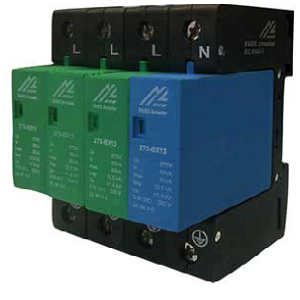
Surge arrester IHE1-275-BC07-1P0
| model name | Type | Uc (V) | In(KA) | Imax(KA) | Iimp(KA) |
| IHE1-275-BC07-1P0 | B+C | ۲۷۵ | ۲۰ | ۴۰ | ۷ |
applications of sure arresterIHE1-275-BC07-1P0:
Surge arrester IHE1-275-BC07-1P0 is used for low-voltage power supply system protection against surges at the boundaries from lightning protection zone 0-2.
In energy transmission and distribution system, transient over-voltage caused by two kinds of major sources. First kinds are external resources that their most samples are thunderbolt. Internal factors also produce other kind of transient over-voltage like switching, load rejection,… .
Protecting the electrical equipment in front of these over-voltages, it’s recommended to use kinds of surge arresters. There are different methods for limiting the over-voltages. Using lightning on the buildings, for example (or installing of the special switches for capacitor banks.
In second stage, using kinds of surge arresters would presented as suitable solution to limit the surface of possible over voltages and protecting the equipment.Finally, it’s necessary also to design the network equipment with suitable dielectric strength.
The Surge protective devices (SPD) are used to limit the maximum over-voltages in low voltage systems and in fact they are the same metal zinc oxide surge arresters with proper design for LV systems. Using these SPDs in LV systems in addition to avoid burning the system insulators in transient high amplitude waves, slow the aging of insulators by frequency of transient & low amplitude waves and increases the useful life of insulators.
Standard and Classifications of S.P.D (surge protection device):
SPDs are classified into three practical class based on their installation place, which named 1 , 2 , and 3 according to standard IEC61641-1 and EN61643-11 and are called B , C , and D in standard DIN VDE 0675-6. Here , we use standard IEC to produce the SPDs .
Structure and Function of SPDs:
Principle and protective function of SPDs is base on non – liner voltage – current characteristic of their varistor. Below figure shows the internal structure of a SPD. According to this figure , you can see a heating fuse which is located in series with internal varistor to disconnect the created short circuit in case of eventual varistor burning. The marker in SPD would discolor too and exchange from green to red.

To see Data Sheet of this product, please click here.


Reviews
There are no reviews yet.